

Friday, April 19, 2013
Quite Universal Circuit Simulator

 Qucs[Quite Universal Circuit Simulator] is free circuit simulator with graphical user interface and power full features.Qucs support all kind of circuit simulation types,like DC, AC, S-parameter, Transient, Noise and Harmonic Balance analysis. Pure digital simulations are also supported.
Qucs is an integrated circuit simulator which means you are able to setup a circuit with a graphical user interface (GUI) and simulate the large-signal, small-signal and noise behavior of the circuit. After that simulation has finished you can view the simulation results on a presentation page or window.
Friday, April 12, 2013
Logisim-Logic Circuits Simulator

Logisim is a simple but powerful software for making or simulating digital logic circuits.With its simple toolbar interface and simulation of circuits as you build them, it is simple enough to facilitate learning the most basic concepts related to logic circuits. With the capacity to build larger circuits from smaller sub circuits, and to draw bundles of wires with a single mouse drag, Logisim can be used (and is used) to design and simulate entire CPUs for educational purposes.
Tuesday, March 5, 2013
PartSim

Friday, February 22, 2013
Circuit Maker 6 Professional
![Circuit Maker 6 Pro[www.techelex.com]](https://blogger.googleusercontent.com/img/b/R29vZ2xl/AVvXsEhVaElr0lNLANgiyZTAjnxmGNUO_UN3VkYDi29cQhP0uKkMDHjKOyaRn7Cn9Ibd0HMmSJAVibmqFRV3qWwSICZFN9x1fxoJTKoKWXIX-kcEzgMpx6VlVL3li8pGkW11oHfiAVESwIS0GOXs/s1600/Circuit+Maker+6+Pro%5Bwww.techelex.com%5D.jpg)
Thursday, June 21, 2012
Spicy Circuit Schematics & Simulation

The first and only circuit schematic capture and simulation program to offer an intuitive, touch-based schematic capture system with real spice simulation capability.
Spicy Schematics is the latest in circuit design. Create, edit, and simulate circuits on your iPad, and sync your files from any Mac or PC using Spicy for Web! … Advanced features such as the Online Circuit Library, and Spice Model Upload Service make Spicy way ahead of the curve. Check out our videos on YouTube, User Manual, Example Circuits Page, and FAQ for more info!
Tuesday, June 12, 2012
FidoCadJ

No need to spend lots of money in acquiring complex and big software to draw simple circuits. Moreover these software can occupy huge amounts of disk space and slow down your system considerably. Eliminate all such issues by just switching to FidoCadJ!
Monday, June 11, 2012
Circuit Diagram Maker

Saturday, March 17, 2012
PowerEsim - SMPS Switching Power Supply

PowerEsim- Free on-line switch mode power supply SMPS, circuit and transformer design, calculation, simulation software. More than 100 circuits and topologies are available with real constructed transformer.
It provides a virtual laboratory environment for users to wind and place every single turn of a transformer, and with the help of tens of thousands real modeled component on the market, user can simple pick and place the real component and stuff into the circuit, within a fraction of a second, our server will immediately return the result to the user.
SweepGen – Turn PC into an Audio Oscillator

SweepGen turns a PC into an Audio Oscillator and Sweep Generator which can be used for testing audio or educational purposes. In conjunction with audio test instruments, you can make frequency response plots. SweepGen uses the sound card in your PC to produce sine waves that are mathematically correct almost to CD quality, indeed it's more likely that the quality of your PC sound card will be the limiting factor rather than the code in SweepGen.
CircuitLab - browser-based schematic editor and circuit simulator

With CircuitLab you can sketch your circuits as easily as you would on a piece of paper, and then simulate your circuit right in your browser to see how it would work in real life! You can then tweak, design, and iterate — all in one tool, all in your web browser.
CircuitLab has powerful SPICE-like device models, and the simulation engine supports mixed-mode analog and digital components side-by-side, so you can rapidly test your ideas for a wide range of possible projects. In addition to DC calculations and time-domain simulation,
Thursday, December 8, 2011
MiscEl – A program with lots of electronic calculation

The program contains a lot of pages with different electronic calculations. Each page contain one or more different calculations. The program is free to download and use, but the program is timelocked. A new version will have to be downloaded after about 1/2 year
MiscEl – A program with lots of electronic calculation
Friday, May 13, 2011
PC Based Signal Generator

Advantages of PC based signal generator: -
1. Low cost, no need to spend lot of money (costs about Indian Rs.30 = US$0.67 = costs almost nothing).
2. Can generate complex signals, like Sin(f1) + Sin(f2). Any function that you can write and understand its limits can be generated from PC.
3. Easier to operate, because, most people who finds signal generator useful are well versed in computer software + hardware.
4. If you use a output buffer amplifier, the chances of damaging your PC sound card is very small. In other words, it is safe.
5. Portable i.e only laptop is needed. Do not need to carry one more signal generator.
6. Use PC sound card, unless you listen to lot of music while working on electronics stuffs.
Disadvantages of PC based signal generator: -
1. Might damage your Sound card (and/ or) PC if you do not understand the limits and do not understand what are you doing.
2. Cannot generate frequencies higher than 20KHz (or slightly higher).

Simplest form of of PC based signal generator: -
go for the PC based function generator by generating the frequencies using the audacity software: -
http://audacity.sourceforge.net/
Once you install the software, it has a menu to generate a "tone". Just select the frequency you need and then PC generates the output (from the audio jack).

Searching the audacity menu, I could not find an option to add DC offset. Then I tried with MATLAB by writing a function to generate sine wave with DC offset, but still no help (read towards end of page to generate signals with MATLAB). Searching the internet, I found that it is actually a feature of sound card, by which it can eliminate any DC offset before the signal comes out. The main purpose is that audio signals with DC offset does not work good on speakers as they simply drive DC current without doing any vibration (which produces the sound). Moreover, DC offset reduces the dynamic range of a signal.
Observe the waveform below as how the sound card removes DC offset, when I tried generating a rectified sine wave (asb(sine()): -

In this picture, initially, the DC offset is present in the waveform. But as time progresses, the sound card removes the DC offset and signal becomes centered around the GND.
To add DC offset, I made a simple circuit which uses LM358 as non inverting summing amplifier. The circuit works good and is tested well with different frequencies. Moreover, this circuit (non inverting amplifier) acts as a buffer between the PC sound card and the external circuit. Hence it can supply the required current without loading the PC sound card.
DC_OFFSET --> This voltage source can be replaced by a pot which can be varied to generate different voltages.
OPAMP_GAIN --> Replace this fixed resistor with pot to get different amplifier gain.
330ohms + 2 diodes --> Used to clamp the output of amplifier between 0V and 5V (almost, ignoring the non rail to rail limitation and diode drops).
These are some pictures of circuit: -


% code for generating sine wave of 1000Hz for 5 sec
t=linspace(0,4,50000);
y = sin(1000*2*pi*t);
sound(y, 10000);
% code for generating sine wave of 400Hz + 1000Hz for 4 sec
t=linspace(0,4,40000);
y1 = 0.5 * sin(400*2*pi*t);
y2 = 0.5 * sin(1000*2*pi*t);
y = y1 + y2;
sound(y, 10000);
% code for generating sine wave of 800Hz for 5 sec and half amplitude
t=linspace(0,4,50000);
y = 0.5 * sin(800*2*pi*t);
sound(y, 10000);
% code for generating full wave rectified sine wave of 1000Hz for 5 sec
t=linspace(0,4,50000);
y = abs(sin(1000*2*pi*t));
sound(y, 10000);
---------------------------------------------------------------------------------------------------------
As you can see, using MATLAB + PC sound card + circuit above, you can generate any signal you want. Only you need to imagine the signal, find its function and type into MATLAB.
The scope capture below shows the time domain and frequency domain analysis of complex signals generated: -
1000Hz Sine wave output: -


Complex waveform of 1000Hz + 400Hz Sine wave output (like DTMF waveform): -

Note that the 2 frequencies are generated faithfully without any extra harmonics (within our band of interest).


Saturday, October 30, 2010
Resistor Calculator 1.0
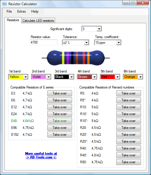
By using this resistor calculator it is very simple to determine the color code of a resistor based on the resistor value.Of course, you can also provide a color code and the program will show you the resulting resistor value.
On the basis of the entered or calculated resistor value additionally the closest resistor within the E series as well as within the Renard numbers is displayed automatically.
As another feature the program can calculate the required resistor value for LED circuits (single LED, series connection and parallel connection) considering the supply voltage, the voltage drop across the LED(s) as well as the current of the LED(s).
FreePCB
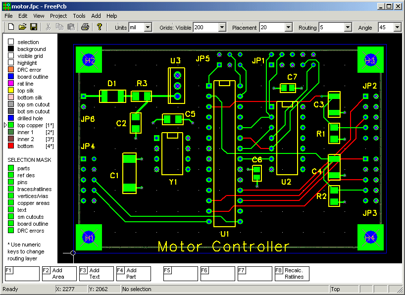
FreePCB is a free, open-source PCB editor for Microsoft Windows, released under the GNU General Public License. It was designed to be easy to learn and easy to use, yet capable of professional-quality work. It does not have a built-in autorouter, but it can use the FreeRoute web-based autorouter at www.freerouting.net. Some of its features are:
- 1 to 16 copper layers
- Board size up to 60 inches by 60 inches
- Uses English or metric units (i.e. mils or mm) for most functions.
- Footprint libraries courtesy of Ivex Design International, PCB Matrix and the IPC.
- Copper fill areas
- Footprint Wizard and Footprint Editor for creating or modifying footprints
- Imports and exports PADS-PCB netlists
- Exports extended Gerber files (RS274X) and Excellon drill files
- Design rule checker
- AutosaveGo Author Website: http://www.freepcb.com/
Wednesday, October 13, 2010
Solve Elec
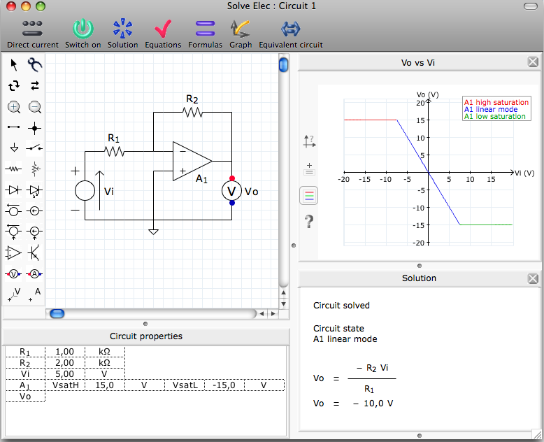
- draw and analyze electrical circuits functioning in direct or alternating current
- get literal formulas and values for current intensities and voltages defined in the circuit.
- verify circuit related equations.
- draw graphs.
- get the equivalent circuit of displayed circuit
- browse an integrated documentation
- edit, save and print reports made of various elements displayed in main window
New in version 2.5 :
- analysis of circuits in AC
- oscilloscope
- filter analysis
- formulas and values of transfer functions
- frequency response graphs
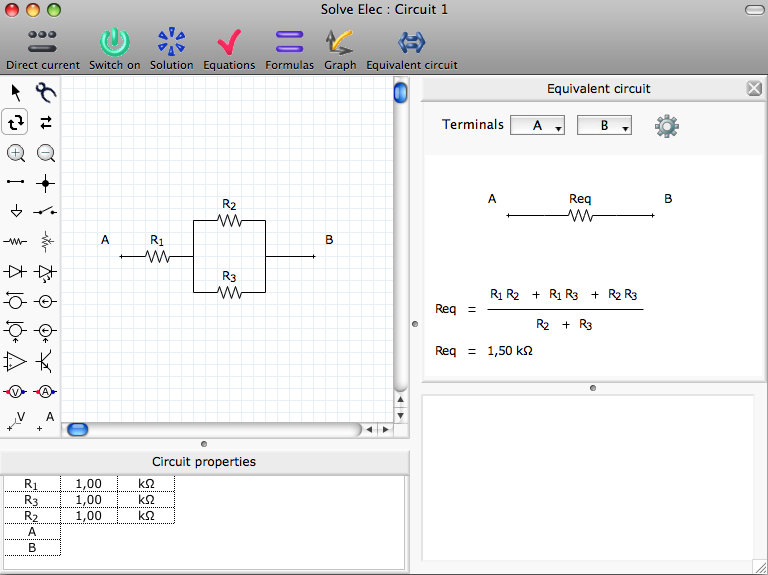

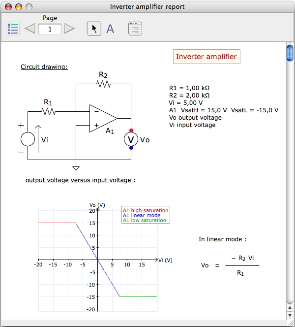
Application documentation :
Download From Here:

Solve Elec 2.5 for Windows 3,2 Mo
Circuits examples
Thursday, September 30, 2010
Express-PCB(Free_Ware)

Best of all, its Free!
ExpressPCB includes ExpressSCH for drawing schematics and ExpressPCB for circuit board layout. he software is easily installed, and a snap to learn and use. Both run with Windows XP through Windows 7.